SmartBite
SmartBite System Architecture Overview
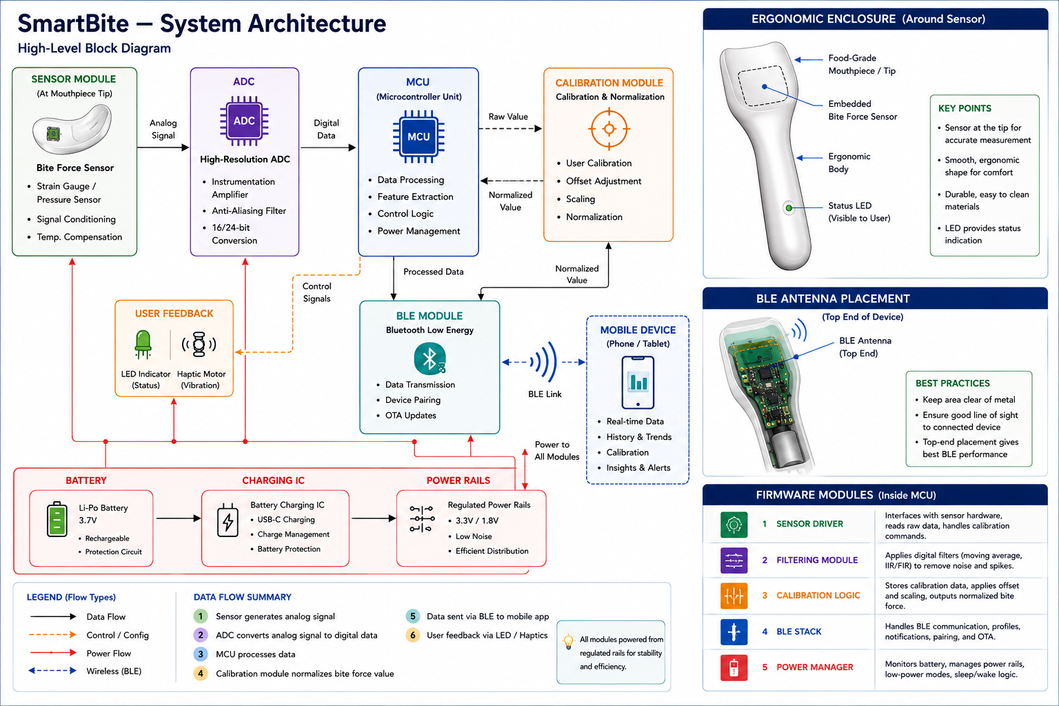
This document provides a high‑level overview of the SmartBite system, describing how all major subsystems interact. It serves as the foundation for firmware, hardware, and ergonomic design decisions.
 —
—
1. System Components.
- Bite‑force sensing module
- Microcontroller (MCU)
- BLE communication module
- Power subsystem (battery + charging IC)
- Calibration subsystem
- User feedback (LED, haptics — if applicable)
2. Data Flow
Full pipeline description:
- Sensor → ADC → MCU processing
- Calibration → normalized force value
- BLE packet creation → transmission
- Mobile app / receiver interpretation
3. Firmware Architecture
- Sensor sampling loop
- Filtering + noise reduction
- Calibration logic
- BLE GATT services
- Power management
4. Hardware Architecture
- Sensor placement
- PCB block diagram
- Power routing
- BLE antenna considerations
5. Ergonomic Integration
- How the electronics fit into the mouthpiece
- Comfort + safety considerations
- Material constraints
- BLE antenna considerations
Acceptance Criteria
- Architecture diagram added to
/docs/architecture/ - Markdown document created:
system_architecture.md - Diagram exported as PNG or SVG
- Linked from the main README